Software program details
General
Consideration in memory: The current track is stored in a char buffer of size 80000. Since the sampling and output frequency are both 8k Hz, this buffer size corresponds to 10 seconds. That is, our looper is capable of recording and layering on top of a track of maximum length 10 seconds. This buffer is stored in Pico’s RAM, which has a capacity of 256 kB. Since the buffer is 800000 bytes in size, corresponding to 80kb, it occupies a rather significant amount of RAM, considering that there are a number of other variables we monitor for. We therefore introduce external memory FRAM to implement functionalities in saving recorded tracks.
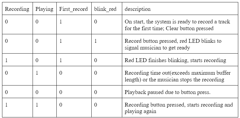
Considerations in state transitions: There are four state variables: recording, playing, and first_record, and blink red. These states are changed by both button presses and logic within the code. Since button presses are not the only source of change in state, and one button press does not necessarily corresponds to only one change, tthere are a bit more logic to consider when buttons are pressed. For example, we do not want to record when the track is not playing. Therefore, on transition of recording state from low to high, if playing is low, we would force it to high. Another example is when we press record for the frist time, the recording state should not become high immediately, since we need the red led to blink first. Therefore, recording would only be set to high after blink_red becomes low.
Valid combination of states (in typical sequence)
Threads
LED
The led_thread is responsible for managing the
LED indicators of the system. It toggles the LED based on the states. The red LED indicates whether or not
the system is recording. The green LED indicates whether or not the system is playing. The yellow LED
indicates whether or not the track is ready for first-time record and/or recording for the first time.
The red LED also flashes three times right before the start of first-time record so that the musician can
get ready, and a blink_red state is set accordingly. Whenever blink_red is high, playing is set to low,
recording is set to low, and the red LED would turn on for half a second, off for half a second and repeat
three times. The delay is implemented with sleep rather than YIELD since we do not want any button presses
and releases to be detected during this period, which might interfere with the states and cause the program
to enter an invalid combination of states.
Serial
The serial_thread handles serial communication to
save track to FRAM and play tracks saved in FRAM based on user input. User can first enter either ‘save’ or
‘play’, then select the track number they would like to save or play.
On a save operation, a file is first opened, then the buffer is written into the opened file using fWrite(). Finally the file is closed. We use an array
of int to track the length of the tracks saved to each file in FRAM so that when it gets played, the loop
has the appropriate length. This list is updated when a track is saved.
On a play operation, the file is first opened, and data in the file is written into the buffer, and lastly
the file is closed. The length is fetched from the array and stored into track_length variable. If a track selected for play
has not been saved before, the data will not be loaded into the buffer, and there will be a prompt to let
the user know.
IRQ handler
Timer interrupt
The timer interrupt is set up to be serviced at a frequency of 8k Hz, corresponding to the sampling rate
and the rate at which data is sent to audio jack through DAC.
If the system is playing, the data in appropriate position will be sent to DAC, in order to be played by the
speaker. Note that the data is sent before being modified, in the case that the track is also in recording
mode. This is due to the fact that we have one of the two channels of the speaker connected to the amplified
guitar sound directly, and the other channel connected to DAC output.
If the system is currently in recording, then data will be read from Pico’s onboard ADC, right-shifted by 3
bits (since the last 3 bits are all noise). If we are recording a track for the first time, the ADC data
will be directly stored in the appropriate position in the buffer. Otherwise, the current data in buffer and
ADC data will be halved then added, in order to prevent overflow.
When the system is recording for the first time, there is a track_length_counter to keep track of the number of
samples taken on the first record. If the counter exceeds length of the buffer, then the track_length is set
to be length of buffer, and the first record would end. In later playing and recording, a track_position is incremented when the system is
playing, and reset when it reaches track_length.
GPIO interrupt
We monitor for falling edge on the three buttons, and change the state based on input and the current state
(much like a mealy machine). One interesting note is that the Pico SDK does not support having multiple
service routine for GPIO interrupts (so one routine for each button is now allowed). Instead, we need to
handle all gpio interrupt in one routine and service the interrupt based on the channel that triggers the
interrupt. The most important thing we need to make sure is that we never enter an invalid combination of
states, since the system would have unpredictable behavior in such cases.
If play is pressed, the state of playing is simply flipped. And after the modification, if the system is not
playing, recording will also be set to low.
If clear is pressed, playing, recording, and blink_red are all set to low, and first_record is set to high.
Everything in buffer is cleared, track_length counter and track_length is resetted.
If recording is pressed, we first determine if this is the track’s first time recording and if the track is
currently recording or not. If the track is not currently recording, then first recording is started.
Otherwise, the first recording is ended and track_length would be updated to match track_length_count. If the track is not in its first
recording, then recording is simply toggled, and playing would be turned on if recording is high after being
toggled.
Be sure to specifically reference any design or code you used from someone else.
Amplifier circuit https://www.tomshardware.com/news/raspberry-pi-pico-guitar-midi-converter
Fram code https://people.ece.cornell.edu/land/courses/ece4760/RP2040/C_SDK_memory/index_memory.html
Things you tried which did not work
Bandpassing signal from dac before feeding into speaker jack
We think this was because the values of R and C aren’t right and resulting in a wrong cut-off frequency. It
failed because, after bandpassing the signal, we couldn’t hear anything outputting from the speaker.
Gpio_set_irq_enable_with_callback ignores the GPIO parameter, event on different gpio would enter the same
handler LOL
Therefore we combined the GPIO callback functions into one and used conditional statement to determine which
one is interrupting the program and to service which GPIO.